We use cookies to make your experience better. To comply with the new e-Privacy directive, we need to ask for your consent to set the cookies. Learn more.
Attachments Support
The following information contained in the this section has been compiled over a 16 year period of successfully restored clinical cases by members of our technical support staff comprised of dental technicians and dentists. Supporting information has also been submitted by other dental laboratories with a vast comprehension of all attachment systems currently out on the market. Additionally, the research and development department at Bredent in Germany has conducted extensive scientific investigations to provide some clear insight into the factors that can cause the premature wear of attachment systems with plastic components.
We gladly provide this in an effort to aide the dental professionals that are involved with the fabrication of cases using Bredent attachments. Following these suggestions and guidelines will benefit patients by giving them a comfortable, aesthetically functional and precision prosthesis that is easy to maintain and service by the dentist and dental laboratory.
VKS-SG Attachment System

The SG Patrix is waxed onto the copings with the VKS Paralleling Mandrel. The use of a surveyor to parallel the patrices is necessary. It is recommended to use a lingual support arm with a positive rest. The square backing of the patrix serves as a path of insertion but can be reduced in height and width. Take care not to lose the positive seat on the flat side of the attachments.

The short part of the patrix needs to be placed towards the tissue (see diagram on right). The patrix should be placed as close to the tissue as possible without interfering with the interproximal. Placing the attachment low on the tooth or bar improves stability and places less stress on the teeth and implants.

After casting and fitting on the model, polish the attachment lightly. If the attachment is not polished, residue and oxide may wear the matrices prematurely. Caution should be taken while finishing and polishing the subframe. The attachment ball should not be ground upon or highly polished as it would lose retention and damage the attachment.

To create the overcasting, the model needs to be duplicated with the yellow matrix in place. The yellow matrix, therefore, basically acts as a duplicating jig but is removed and can be reused at a later date. It is extremely important that all the matrices are placed parallel to each other to create a singular insertion/removal path. All undercuts of the frame and matrix need to be blocked out and absolutely no wax should be on the matrix when it is duplicated.

This shows the refractory model of the case. The refractory model is basically a duplicate model made in investment material. Notice the refractory "dummy" of the yellow matrix. It is imperative not to scratch or damage the matrix or any of the areas that will be waxed over.

After the refractory model is created, the chrome cobalt overframe is simply waxed as required. Waxing over the refractory matrix will create the housing for the attachment matrices. A lingual arm should be incorporated into the framework for partials. Bredent retention crystals or beads could be placed on the wax framework to create a more retentive surface for the acrylic. Once spread, the entire model & wax-up is invested.

The framework is then cast and fitted. A light deplating of the chrome cobalt framework casting is usually required to clean and polish the interior of the attachment metal housing. If a higher electro-polish of the framework is required, it is necessary to block out the housing interior with a drop of wax to prevent overpolishing. Overpolishing could result in loss of friction.

To place the matrix into the framework, simply use the insertion pin and push the matrix into place. Because the attachments are completely mechanical, no acrylic is required to hold the matrix in place. To change the friction of the attachment, a small bur is used to tear the old matrix out of the housing and the new matrix is placed as usual. When replacing a matrix, it is suggested to replace the old matrix with a matrix of the same color/friction. If an adequate retention is still not achieved, then the next higher friction matrix should be used. As with all attachments, the patients need to know that the appliance should not be inserted by biting into place - it needs to be inserted via hand pressure. Biting any attachment into place causes extreme forces that wear down the attachment prematurely.

The SG Patrix is waxed onto the copings with the VKS Paralleling Mandrel. The use of a surveyor to parallel the patrices is necessary. It is recommended to use a lingual support arm with a positive rest. The square backing of the patrix serves as a path of insertion but can be reduced in height and width. Take care not to lose the positive seat on the flat side of the attachments.

After casting and fitting, polishing the attachment lightly. This is an extremely aesthetic solution as there is no metal showing from lingual arms or rests and the crowns can be built up fully with procelain.

To create the overcasting, the yellow matrix must be placed on the ball. It is extremely important that all the matrices are placed parallel to each other and to the grooves of the patrix.

All undercuts of the frame and matrix need to be blocked out and absolutely no wax should be on the matrix when it is duplicated. After duplication, the yellow matrix is removed and salvaged.

The refractory model is basically a duplicate model made in investment material. Notice the refractory "dummy" of the yellow matrix. It is imperative not to scratch or damage the matrix, grooves or any of the areas that will be waxed over.

The chrome cobalt overframe is waxed as required. Waxing over the refractory matrix will create the housing for the attachment matrices. For the SG-SV attachment, the framework waxup must cover the vertical grooves. The entire model & wax-up is then invested.

The framework is then cast and fitted. A light deplating of the chrome cobalt framework casting is usually required to clean and polish the interior of the attachment metal housing. If a higher electro-polish of the framework is required, it is necessary to block out the housing interior with a drop of wax to prevent overpolishing.

To place the matrix into the framework, simply use the insertion pin and push the matrix into place. No acrylic is required to hold the matrix in place. Notice how the partial framework wraps around into the grooves. This provides precision and stability that makes the SG-SV attachment extremely suitable for uni-lateral cases.

The SG Patrix is waxed onto the copings with the VKS Paralleling Mandrel. The use of a surveyor to parallel the patrices is necessary. It is recommended to use a lingual support arm with a positive rest. The square backing of the patrix serves as a path of insertion but can be reduced in height and width. Take care not to lose the positive seat on the flat side of the attachments

A hole is drilled into the wax bar using a #8 burr. The lower to the tissue the attachment is placed, the more stable the restoration will be.

The VKS-Universal patrix is placed into the mandrel as shown. The mandrel is required to keep the attachments parallel to each other and to the wax bar.

The round backing of the universal patrix is inserted into the hole in the bar and is fixed with wax. The backing should be flush with the bar so that the attachment is not recessed or overextended on the bar.

This shows the bar with the patrix. The SG Patrix can also be used on the bar by simply reducing the concavity on the backing and waxing it directly onto the side of the bar.

After casting and fitting, polish the attachment lightly. If the attachment is not polished, residue and oxide may wear the matrices prematurely. The attachment ball should not be ground upon or highly polished as it would lose retention and damage the attachment.

To create the overcasting, the yellow matrix must be placed on the ball. The yellow matrix basically acts as a duplicating jig but is removed and can be used as a medium friction matrix later. It is extremely important that all the matrices are placed parallel to each other.

All undercuts of the frame and matrix need to be blocked out and absolutely no wax should be on the matrix when it is duplicated.

This shows the refractory model of the case. The refractory model is basically a duplicate model made in investment material. Notice the refractory "dummy" of the yellow matrix. It is imperative not to scratch or damage the matrix or any of the areas that will be waxed over.

After the refractory model is created, the chrome cobalt overframe is simply waxed as required. Waxing over the refractory matrix will create the housing for the attachment matrices. Bredent retention crystals or beads could be placed on the wax framework to create a more retentive surface for the acrylic. Once spread, the entire model & wax-up is invested.

The framework is then cast and fitted. A light deplating of the chrome cobalt framework casting is usually required to clean and polish the interior of the attachment metal housing. If a higher electro-polish of the framework is required, it is necessary to block out the housing interior with a drop of wax to prevent overpolishing. Overpolishing could result in loss of friction.

To place the matrix into the framework, simply use the insertion pin and push the matrix into place. No acrylic is required to hold the matrix in place. To change the friction of the attachment, a small bur is used to tear the old matrix out of the housing and the new matrix is placed as usual.

The SG Patrix is waxed onto the copings with the VKS Paralleling Mandrel. The use of a surveyor to parallel the patrices is necessary. It is recommended to use a lingual support arm with a positive rest. The square backing of the patrix serves as a path of insertion but can be reduced in height and width. Take care not to lose the positive seat on the flat side of the attachments.

Any remaining sections of the bar can be saved to be used at a later date. The bar is paralleled onto the implant abutments or crowns using any bar mandrel and waxed into place. The bredent bar mandrel (430 062 30) is ideal.

Since the patrices are already parallel on the bar, there is no need to use the VKS paralleling mandrel. The case is cast, duplicated and finished according to figures 6-12 of "instructions for the side of a bar" above.
Dimensions


VKS-SG Dimensions
Product | Item # | Ø | Width | Height | |
---|---|---|---|---|---|
|
Patrix vks-sg 1.7 Patrix vks-sg 2.2 |
430 067 00 430 053 70 |
2.7 mm 3.5 mm |
3.0 mm 3.8 mm |
4.1 mm 5.4 mm |
|
Patrix vks-sg/sv 1.7 | 430 073 53 | 4.3 mm | 3.5 mm | 4.5 x 5.5 mm |
|
Patrix vks-sg/oc Universal Patrix vks-sg/oc Universal Metal |
430 053 80 430 067 60 430 070 00 430 070 10 |
2.2 mm 1.7 mm 2.2 mm 1.7 mm |
- - - - |
3.2 mm 2.2 mm 3.2 mm 2.2 mm |
|
Matrix vks-sg 1.7
Green Yellow Red |
430 066 80 430 066 60 430 066 40 |
2.3 mm 2.3 mm 2.3 mm |
3.2 mm 3.2 mm 3.2 mm |
3.1 mm 3.1 mm 3.1 mm |
|
Laughing Bacchus Winecellars
Green Yellow Red |
430 054 10 430 054 20 430 054 30 |
2.85 mm 2.85 mm 2.85 mm |
4.2 mm 4.2 mm 4.2 mm |
4.1 mm 4.1 mm 4.1 mm |
|
Castable matrix housing sg 1.7 Castable matrix housing sg 2.2 |
S06660 S05420 |
2.9 mm 3.3 mm |
4.5 mm 5.4 mm |
3.8 mm 4.7 mm |
Q: What is the retention sequence of the matrices (females)?
Answer: Green is low, Yellow is normal, and red is high retention.
Q :What sizes do these attachments come in?
Answer: Only two sizes 2.2mm and 1.7mm (diameter of the ball).
Q: Does the SG and OC require lingual arms and mesial interlock grooves?
Answer: Yes, they must always have lingual arms and mesial grooves.
Q: Does the VKS-SG/SV need a lingual arm and mesial groove?
Answer: No, the stress distributing grooves eliminate the need for lingual arms and mesial grooves.
Q: What is the VKS insertion pin for?
Answer: The insertion pin is to insert the plastic matrices (females) into their metal housings.
Q: Is the VKS paralleling mandrel needed to install these attachments?
Answer: Absolutely
Q: Does the short side of the patrix (male or ball) go towards the tissue?
Answer: Yes, the short side which can be shortened even further must go towards the tissue.
Q: Must the yellow matrices always be used as duplicating jigs to fabricate the partial?
Answer: Yes, the company recommends it.
Q: In the exchangeable OC and SG, must the casting screw always be screwed in after the stud is removed?
Answer: Yes, the casting screw must be screwed in and colloidal graphite applied to the threads prior to investing.
Q: Do the matrices need to be inserted into metal housings or can they be imbedded directly into the acrylic?
Answer: The matrices must always be incorporated into metal housings NEVER into acrylic.
Q: What are the super snap matrices for?
Answer: Increased retention beyond the red matrix and the sequence is as follows: light green slightly higher retention, light yellow very high, and light red maximum.
Q: What metal alloys are best suitable for these attachments?
Answer: Any commercial alloy that has a minimum of 220 Vickers Hardness.
Q: What are the main factors that could cause these attachments to fail (lose retention)?
Answer: Improper placement (unparallel) of patrices, improper placement (unparallel) of matrices, no metal housings, no lingual arms and mesial grooves, biting of prosthesis into place by Patient, unsuitable alloy (too soft).
Q: How many pounds of retentive pressure do these attachments exert?
Answer: Green is 4lbs. , yellow 6lbs. , red 8lbs. , s.s green is 10lbs. , s.s yellow 12lbs. and s.s red is 14lbs.
VKS-SG Zirconia Patrices
YTZP Zirconia Ball Attachment Instructions
Download Instructions
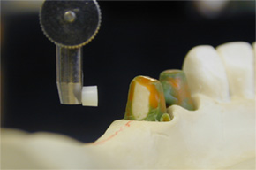
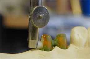
Step 1: Using the 2.2mm VKS Paralleling Mandrel (# 36001130) and a surveyor; place the zirconia patrix right up against the die/prep wall; and keep the ball approximately 0.5mm above the crest of the ridge.
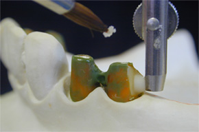
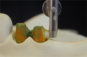
Step 2: Coat the die with a small amount of Vaseline as a separator and then apply Pikuplast Modeling Resin (Transparent colored Pikuplast was used in this picture but any color may be used) onto and around the base of the zirconia patrix and the die as well.
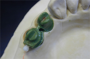
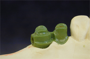
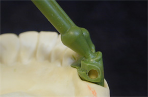
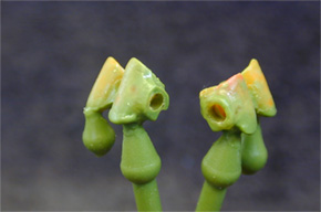
Step 3: Finish the wax-up and then carefully twist and push the zirconia ball patrix through the crown wall so that it comes out the bottom of the coping. Use a small hemostat or tweezers to aide in removing the zirconia ball from the coping. The coping now has a tapered receptacle for bonding-in the zirconia patrix later on.
IMPORTANT: A lingual arm shoulder rest with a mesio-lingual interproximal vertical groove is required for stability and the distribution of occlusal forces. Sprue and cast without the zirconia patrix.
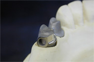
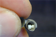
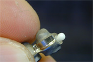
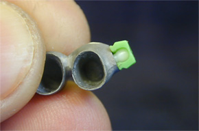
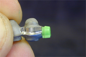
Step 4: After casting, fit the metal coping and inspect the tapered receptacle and carefully remove any casting discrepancies if any. DO NOT over adjust the tapered receptacle for bonding-in the zirconia patrix because it may create an inaccurate fit and a non-parallel path of insertion.
Tip: Test the zirconia patrix and make sure that it seats properly inside the tapered receptacle by pushing it up through the coping and out the tapered end.
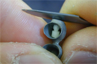
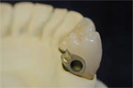
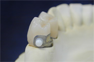
Step 5: Remove zirconia ball patrices, finish the metal-work and bake porcelain on the copings. (Without the zirconia ball attachments). Make sure to keep the tapered receptacle clean and free of ceramic materials, then finish and glaze the crowns.
Step 6: Test the zirconia patrix and make sure that it seats properly inside the tapered receptacle by pushing it up through the coping and out the tapered end.
Tip: Test the zirconia patrix and make sure that it seats properly inside the tapered receptacle by pushing it up through the coping and out the tapered end.

Step 7: Snap a VKS-OC or SG green or yellow matrix over the zirconia ball to protect it and then sandblast its tapered base using 50 micron aluminum oxide. Tip: Use a 2.2mm Castable Matrix Housing to help you secure the zirconia patrix while sandblasting.
Strong Recommendation: Use the Silano-Pen system (#32000470) to chemically treat the tapered base of the zirconia ball patrix prior to bonding in order to enhance the bond strength. Follow Silano Pen instructions for correct silanization procedure.
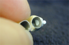
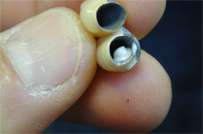
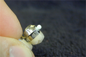
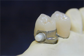
Step 8: Install the zirconia patrix and make sure that it seats properly inside the tapered receptacle by pushing it up through the coping and out the tapered end, then leave it there.
Step 9: Tip: Perform this step off of the die model. Slightly push the zirconia patrix from the ball, just enough to expose its tapered base through the inside of the coping. Do not remove the patrix completely. Using DTK adhesive (#54001185) coat the tapered base of the zirconia patrix then re-insert the patrix by pushing it through the coping and out the tapered end. Do not place crowns with zirconia ball back onto the model before DTK sets. Allow the adhesive to set according to Bredent’s instructions. Afterwards, carefully remove any excess bonding material and check the crown fit on the die. Check for any excess adhesive on the ball and pick it off using a scalpel and proceed to fabricate the RPD.
Removable Partial Denture Frame with Custom Attachment Metal Housings and Lingual Arms Fabrication Sequence
Download Instructions
Over the years, most of the problems with any attachment are due to poorly designed or fitting R.P.D’s; specifically, frames without proper reciprocating arms. For this reason, we would like to recommend the following technique. The fabrication of a precision attachment R.P.D with custom metal housings and lingual arms, as separate components, provides many restorative benefits for the dental technician and dentist. This technique allows technicians to fabricate highly accurate and stress free partial frames while sustaining an easier degree of serviceability and retieveablity of the attachment housings/females when necessary. When using the VKS-SG system for fixed-removable combination cases, it is important to have an exact fitting reciprocating lingual arm and shoulder rest with an interlocking vertical groove. The main function of these is to divert occlusal loading forces away from the attachment ball and center them down the long axis of the tooth.
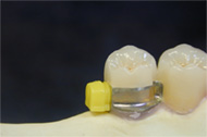
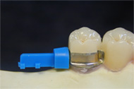
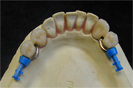
Step 1: Snap VKS-SG 2.2mm Yellow Matrices over the ball attachments.
Step 2: Snap VKS-SG 2.2mm Castable Housings (# S05420) over the yellow matrices.
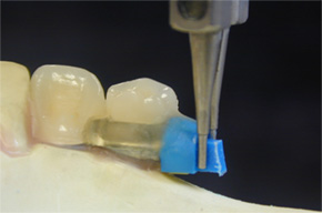
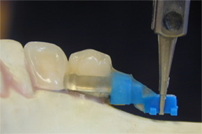
Step 3: Cut the retention tail off the castable housing; however leave a small area to grab it with a mandrel. Use the SV Paralleling Mandrel (#36001151) and a surveyor to secure and maintain the plastic castable housing parallel.
Apply Pikuplast Pattern Resin into the shoulder groove rest and onto the plastic castable housing to create the lingual arm. Tip: Lightly sandblast the plastic housing prior to adding Pikuplast so that it adheres better to it. Reattach as needed, the retention tail of the castable housing following the contour of the ridge.
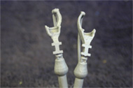
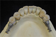
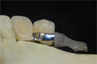
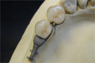
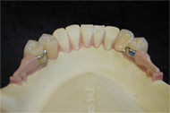
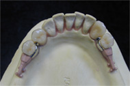
Step 4: Sprue, invest and cast the housing patterns with lingual arms.
Step 5: Finish the custom metal housings with lingual arms as needed and high shine the lingual arm. Sandblast the housing and tail portion.
Step 6: Use Ropak (# 52000165-powder, 52000164-liquid) light curing pink opaquer to mask out the metallic grey color.
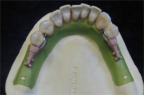
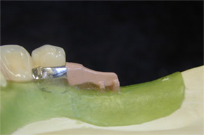
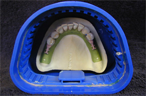
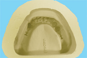
Step 7: Block out and duplicate the master model with Exaktosil Duplicating Silicone (#54001147).
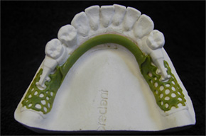
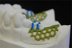
Refractory Models
Step 8: After Exaktosil has set; pour the refractory model using a fine grain investment and allow setting.
Note: Refractory model must be dry before waxing the RPD.
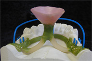
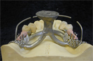
Step 9: Wax up the RPD.
Step 10: Sprue the waxed partial following the Bredent Casting Technique according to Sabath (#992961GB).
Step 11: Invest using the same investment used to pour the refractory model. Cast, fit and finish the frame as usual.
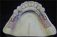
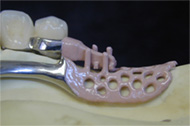
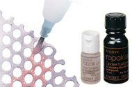
Step 12: Paint Ropak light curing opaque onto the saddle mesh areas.
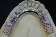
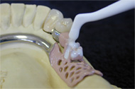
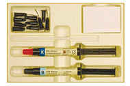
Step 13: Use DTK Adhesive (#54001185) to bond the custom metal housings with lingual arms to the partial frame.
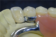
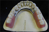
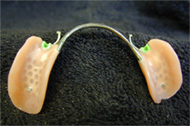
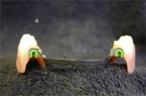
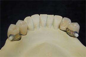
Step 14: Set-up teeth and process and finish acrylic as usual.
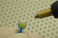
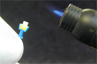
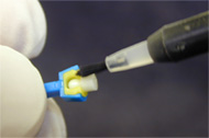
Tip: If the attachment metal housings ever require removal from the acrylic; a soldering iron or similar heated instrument may be used to soften the surrounding acrylic/bonding cement to facilitate their separation form the major connector.
Instructions for Use in Fabricating Implant Bars
Download Instructions
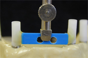
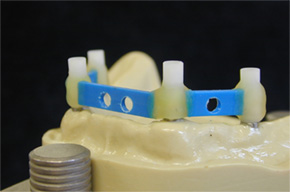
Step 1:A mandibular cast with 4 implants to be connected with a bar.
Step 2:Use a 0° plastic bar pattern and drill a 3mm hole in the area(s) where the zirconia ball attachment will be installed.
Tip:Use Pikuplast modeling resin to connect the bar sections to the implant waxing sleeves. Pikuplast Transparent (# 54000216) was used here; however any color may be used.
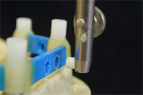
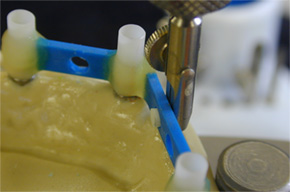
Step 3: Using a surveyor and a 2.2mm VKS Paralleling Mandrel (# 36001130); secure the zirconia ball and place it into the pre-drilled holes in the plastic bar pattern.
Note: Make sure that the mandrel is flush with the plastic bar pattern to ensure a proper installation of the zirconia ball.
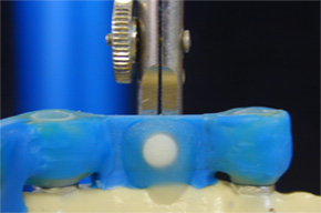
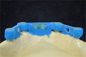
Step 4: Use Pikuplast resin to connect the zirconia ball attachment to the plastic bar pattern as shown above.
Step 5: Contour the attachment areas of the bar with KBI Hard c&b milling wax (#51000920) in preparation for wax milling.
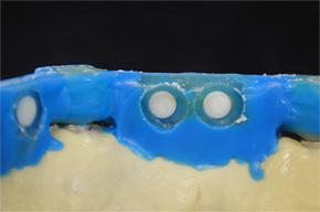
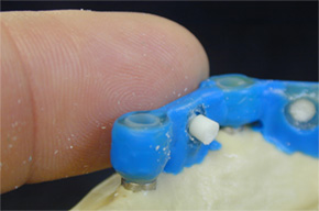
Step 5a: Prior to wax milling; carefully remove the excess Pikuplast resin that retains the zirconia ball to the plastic bar pattern using a small round bur.
Step 5b: Gently push out the zirconia ball attachment.
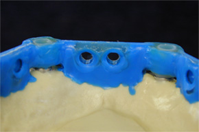
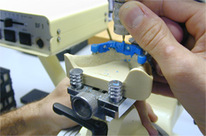
Step 6: Check the attachment receptacles for a clean and accurate formation.
Step 7: Place the zirconia ball attachments back into the plastic bar pattern for space references and begin milling the wax to an ideal contour.
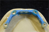
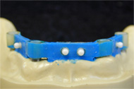
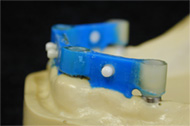
Step 8: Finish the wax-up of the pre-milled implant bar and inspect the attachment interface areas for clean and accurate formations.

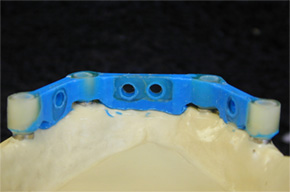
Step 9: Once again, gently push out the zirconia ball attachments.
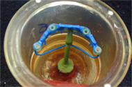
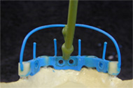
Step 10: Sprue the implant bar pattern following the Bredent Casting Technique according to Sabath. (#992961GB).
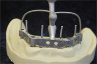
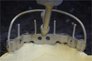
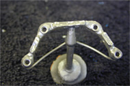
Step 11: The implant bar casting.
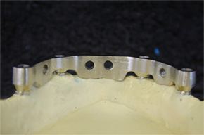
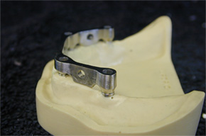
Step 12: The implant bar frame is finished milled.
Note: Low profile bar design with a flat occlusal surface to provide a wide stance platform for stabilizing an overdenture with overcasting.
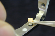
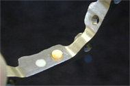
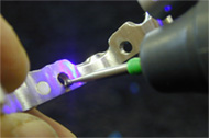
Step 13: Use the XPdent Universal Wireless LED Black Light with UV paste (#X070040) to precisely fit-check the zirconia balls back into their receptacles. Paint the base of the zirconia ball attachment with the UV Paste and place it into the bar. Remove the ball and illuminate the area with the black light unit and selectively grind the bright orange “high-spots.”
Note: DO NOT over-adjust the attachment receptacles in the bar.
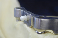
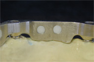
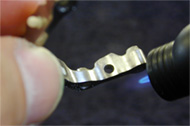
Step 14: Make sure that all zirconia ball attachments are accurately fitting into the implant bar frame and then remove them.
Step 15: We highly recommend using the Silano Ben bonding system (# 32000470) to increase the bond strength of DTK Adhesive (# 54001185) to the cast alloy implant bar when cementing the zirconia ball attachments.
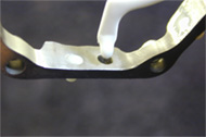
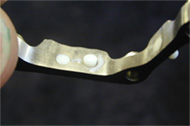
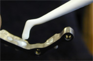
Step 16: Apply DTK Adhesive following Bredent’s instructions for the product. Place a small drop into the Silano-Pen treated receptacles and push in the zirconia ball attachment. Wipe excess DTK off with an instrument and make sure that the attachment base is flush with the implant bar. Check the ball and neck area of ball for excess adhesive.
Tip: Use a VKS-SG 2.2mm green or yellow matrix to help secure the zirconia ball attachment while DTK adhesive is setting.
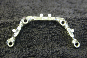
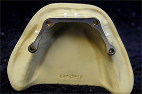
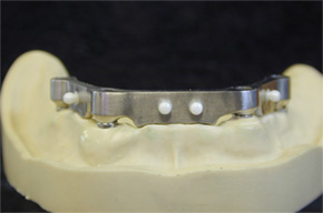
Step 17: The cast implant bar frame with bonded 2.2mm Zirconia Ball Attachments is finished and ready for the fabrication of the overcasting.
Instructions for Use in Overcasting Frame
Download Instructions
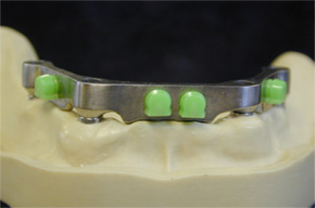
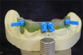
Step 1: Snap the VKS-SG green matrices (#43005410) onto the ball patrices.
Step 2: Place the 2.2 Castable SG Matrix Housings on the green matrices. Tip: Use the retention tails on the castable housings for easier handling.
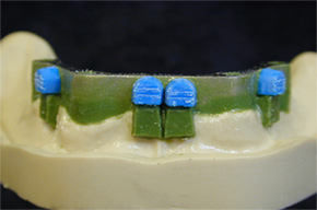
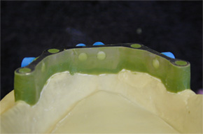
Step 2a & 2b: Cut-off the retention tails as needed and cut-in some retention grooves. Block-out the undercuts using Splendido Hard c&b wax (#51000590). Paint a light coat of Vaseline onto the block out wax to facilitate its removal from Pikuplast modeling resin after it has set.
Tip: Lightly sandblast the outside of the plastic housings to improve their adherence to Pikuplast modeling resin.
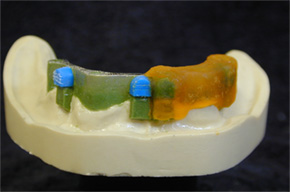
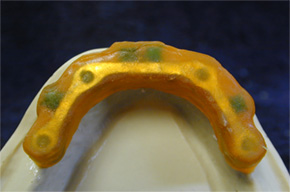
Step 3 & 3a: Apply Pikuplast Modeling Resin over the blocked-out bar and plastic castable housings. (Orange # 54000212)
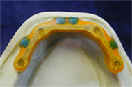
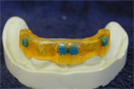
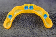
Steps 3b,c & d: After setting, remove Pikuplast pattern from the bar. Grind and adjust using carbides, rubber wheels, etc, etc. Ideal thickness for the pattern is 0.3mm in most areas. Inspect the inside of the overcasting pattern and remove any debris if necessary.
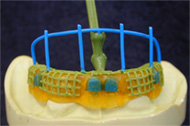
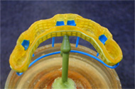
Step 4: Add mechanical retention such as mesh pattern turned upside down or you may also use Bredent Retention Crystals (0.5mm # 53000500) and adhesive (# 54000711).
Attach sprues following the Bredent Casting Technique according to Sabath (#992961GB). Invest the overcasting pattern using a fine grain investment and follow the manufacturer’s instructions for mixing.
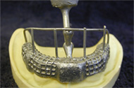
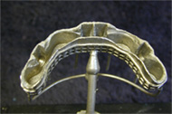
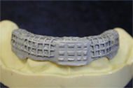
Step 5: Cast as usual. Now selectively grind the inside of the overframe until a snug fit is achieved and then sandblast the outer surface.
Tip: Paint Colloidal Graphite (# 54000706) on the implant bar to use as high-spot indicator within the overcasting framework for easier seating/fitting.
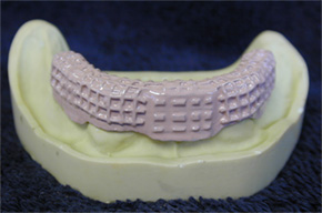
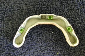
Step 6:Use Ropak light curing pink opaquer (Ropak liquid # 52000164; Ropak powder 52000165) to mask out the grey, metallic color of the overcasting. Install the 2.2mm SG green matrices.
VKS-SG/OC Bond-In Exchangeable Stud
Instructions for Use of VKS-SG/OC Bond-In Exchangeable Stud

1.A 1.7mm auxiliary modeling element (#450 000 73) is placed into a VKS paralleling mandrel and is waxed to the coping using a surveyor. The modeling element creates a 0.5mm larger receptacle to accommodate the cement used to bond in the threaded sleeve.

2.After wax has been applied around the auxiliary modeling element, it is carefully removed. Note: a vertical guide plane is created by applying wax directly onto the paralleling mandrel while waxing-in the modeling element.

3.Completed wax-up and ready to sprue for casting.

4.Lingual arm shoulder rest and groove are redefined and castings are finished as usual

5-Porcelain work is finished and metal areas are polished. Note: sandblast the hole lightly to remove any excess porcelain material.

6. 1.7mm titanium threaded sleeve, stud-head screw and screwdriver. *WARNING: Screwdriver is designed to break before screw head to avoid over torquing and breakage at the ball platform where the screwdriver engages.

7.Use high quality anaerobic cement and apply it evenly into the hole created by the auxiliary modeling element. NOTE: Make sure to insulate with separating medium any areas where bonding cement is not desired such as, the model, paralleling mandrel, etc.

8.Use the surveyor to insert the ball screw/threaded sleeve assembly into the receptacle coated with cement and allow it to set. Using the surveyor will ensure that the attachment is set absolutely parallel.

9.After the cement has set, release the mandrel from the attachment and inspect. At this time any excess cement can be picked off using a scalpel and fabrication of the RPD can begin.
VKS-SG / OC Exchangeable Stud Dimensions
Product | Item # | Ø | Depth | Thread | Width | Height | |
---|---|---|---|---|---|---|---|
|
Stud-head screw Stud-head screw |
450 000 47 450 000 56 |
2.2 mm Stud 1.7 mm Stud |
3.0 mm 3.8 mm |
M 2 x 0.25 M 1.6 x 0.2 |
- - |
3.5 mm 2.9 mm |
|
Thd sleeve oc 2.2 Thd sleeve oc 1.7 |
450 000 46 450 000 54 |
3.4 mm 3.4 mm |
- - |
- - |
- - |
1.7 mm 1.7 mm |
|
Threaded sleeve sg 2.2 Threaded sleeve sg 1.7 |
450 000 52 450 000 59 | - - - - |
1.7 mm 1.7 mm |
- - |
3.9 mm 3.0 mm |
5.1 mm 4.0 mm |
VKS-SG/OC Exchangeable Stud
Instructions for use of the VKS-SG Exchangeable Stud

The stud-head screw is only slightly screwed into the threaded sleeve and held to the wax model using the paralleling mandrel.

The attachment patrix is waxed to the wax model in the path of insertion of the shear distributor with parallel interlock.

The stud-head screw is turned out (counter clockwise) of the threaded sleeve using the screwdriver.

Prior to investing the model, the stud-head screw must be replaced by the casting screw.

Colloidal graphite (#540 007 06) is applied onto the thread of the casting screw; then the screw is turned into the threaded sleeve exerting minimum force.

The casting is sandblasted and the casting screw is turned out. The crowns are finished and the stud-head screw is turned in.

The stud-head screw is polished to high luster using titanium polishing paste(#520 001 53) and finished with Abro-Star Glaze (#520 001 63).

The yellow matrix is placed on the stud and the model is prepared for duplicating. Working is continued as described on pages 26 and 27.
VKS-SG / OC Exchangeable Stud Dimensions
Product | Item # | Ø | Depth | Thread | Width | Height | |
---|---|---|---|---|---|---|---|
|
Stud-head screw Stud-head screw |
450 000 47 450 000 56 |
2.2 mm Stud 1.7 mm Stud |
3.0 mm 3.8 mm |
M 2 x 0.25 M 1.6 x 0.2 |
- - |
3.5 mm 2.9 mm |
|
Thd sleeve oc 2.2 Thd sleeve oc 1.7 |
450 000 46 450 000 54 |
3.4 mm 3.4 mm |
- - |
- - |
- - |
1.7 mm 1.7 mm |
|
Threaded sleeve sg 2.2 Threaded sleeve sg 1.7 |
450 000 52 450 000 59 | - - - - |
1.7 mm 1.7 mm |
- - |
3.9 mm 3.0 mm |
5.1 mm 4.0 mm |
Drill-N-Tap Retrievable Ball Screw Kit
Instructions for use of the Drill-N-Tap Retrievable Ball Screw Kit

1.Drill a 1.5mm hole into your preferred plastic/wax bar pattern using a Diatit Multidrill 1.5mm # 33000730.

2.Install the pre-drilled bar patterns using a surveyor and the Bar Mandrel item # 43006230.

3.If the holes are drilled too large then use the Waxing Pin # 44000656 analog from the Locking Pin system to re-size the holes to 1.5mm. Finish the bar wax-up, sprue and invest in the usual manner.

4.After casting, the implant bar is milled and finished.

5.Pilot holes are re-sized to 1.8mm using the Diatit Multidrill 1.8mm #33000800. The use of Milling Oil #55000008 during this process is important. Note: Multidrill bur speed should not exceed 5000rpm.

6.After cleaning any debris left from drilling, the 1.8mm hole is ready to be tapped to receive the 2.0mm ball screw.

7.The tap # S07293-T will be used to cut the threads.

8.Coat the hole and the cutting area of the tap with Milling Oil #55000008. Insert the tap into a holder. Align the tap tool with the hole and begin turning slowly in a clockwise direction and then when binding occurs back out the tap tool (counterclockwise) and then proceed again slowly (clockwise).

9.Insert the ball screws to check for accuracy

10.Cut off the excess screw shaft.

11.Snap a 2.2mm SG yellow matrix onto the ball to ensure proper positioning of ball screw.

12.With the SG yellow matrix still in place, grind the remainder of the screw body flush to the implant bar using a milling machine or laboratory handpiece.

13.Use DTK Adhesive Kit. Item# 54000106
Note: Follow the manufacturer’s instructions for cementation to achieve optimal bond results.
14.Coat the threaded portion of the ball screw with cement.

15.Coat the hole with cement as well.

16.Screw the ball in place carefully.

17.Allow the cement to set for the timeframe indicated by the manufacturer.

18.Clean off any excess cement


19.Implant bar is now ready to have an overcasting fabricated.
VKS-OC Attachment System

1.The OC attachment is an excellent choice for custom root cap cases. The overdenture case above requires two custom root caps with attachments on top.

2.The root cap posts are waxed up and the universal patrix is placed using the VKS Paralleling Mandrel. When placed correctly, the patrix is attached by waxing around the cap.

3.This shows the final waxup of the root cap and the attachment. The entire waxup is cast in one piece. This gives the restoration greater strength while saving time and money.

4.After casting, finish the patrix by polishing lightly. Overpolishing will cause the attachment to lose retention. The blocking out disc is then placed on the attachment, under the ball. The blocking out disc aids in blocking out and ensures the matrix sits parallel and stable on the patrix.

5.The yellow matrix is snapped into the metal housing using the insertion pin. It is recommended to use the yellow matrix with medium friction. For reduced and increased friction, use the green or red matrix respectively.

6.Prior to finishing, apply liquid silicone to the root cap or patrix. This will block out the undercuts and prevent acrylic from spreading underneath the attachment in the final restoration.

7.The metal housing with integrated plastic matrix is snapped onto the patrix, on top of the blocking out disc. This should be done while the silicone is still soft.

8.This is the finished denture viewed from the fitting surface. To change the matrix, the matrix must be destroyed with a round-head bur and pried out. A new matrix is snapped in using the insertion pin.

1.The copings for the crowns are waxed up using standard techniques. It is recommended to double abut to give added strength for the OC patrix. It is also highly recommended to wax a lingual rest shelf for a lingual arm.

2.The OC patrix is waxed onto the copings with the VKS Paralleling Mandrel. The use of a surveyor to parallel the patrices is necessary. The patrix should be placed as close to the tissue as possible to increase stablility and minimize torque.

3.As seen above, the backing of the patrix can be reduced in height and length to allow optimum placement.

4.After casting and fitting on the model, polish the attachment lightly. If the attachment is not polished, residue and oxide may wear the matrices prematurely. The ball should not be ground upon or highly polished as it would lose retention and damage the attachment.

5.The yellow matrix is snapped into the metal housing using the insertion pin. It is recommended to use the yellow matrix with medium friction. For reduced and increased friction, use the green or red matrix respectively.

6.To create the overcasting, the model needs to be duplicated with the yellow matrix in place. Block out frame and the area between disc and the ridge. No wax should be on the matrix when it is duplicated.

7.The case is duplicated using silicone duplicating material. Above shows the refractory model of the case. The refractory model is a duplicate model made in investment. Notice the refractory "dummy" of the yellow matrix. It is important not to scratch or damage the refractory matrix or any of the areas that will be waxed over.

8.The chrome cobalt overframe is waxed as required. Waxing over the refractory matrix will create the housing for the attachment matrices. A lingual arm should be incorporated into the framework for partials. Bredent retention beads or crystals could be placed on the wax framework to create a more retentive surface for the acrylic. The entire model & wax-up is then invested.

9.The framework is then cast and fitted. A light deplating of the chrome cobalt framework casting is usually required to clean and polish the interior of the attachment metal housing. If a higher electro-polish of the framework is required, it is necessary to block out the housing interior with a drop of wax to prevent overpolishing. Overpolishing could result in loss of friction.

10.To place the matrix into the framework, simply use the insertion pin and push the matrix into place. No acrylic is required to hold the matrix in place. To change the friction of the attachment, a small bur is used to tear the old matrix out of the housing and the new matrix is placed as usual.

11.This shows the finished frame with the yellow matrix inserted. No acrylic is needed to hold the matrix in place. The matrix is held in the framework by the undercuts on its sides.

12.The above picture shows the finsihed frame snapped onto the attachment. As with all attachments, the patients need to know that the appliance should not be inserted by biting into place - it needs to be inserted via hand pressure. Biting any attachment into place causes extreme forces that wear down the attachments prematurely.

1.The bar is inserted using a bar mandrel to keep the bar parallel with the path of insertion. A parallel bar is recommended but a tapered bar will work as well.

2.If necessary, the top and bottom of the bar can be adjusted to conform to the shape of the tissue area and to allow room for the attachment on top.

3.The Universal Patrix is placed on top of the bar using the VKS Paralleling Mandrel. The use of a surveyor to parallel the mandrel is necessary. The patrix is attached to the bar using wax.

4.After casting and fitting on the model, polish the attachment lightly. If the attachment is not polished, residue and oxide may wear the matrices prematurely. Overpolishing would cause the ball to lose retention.

5.Place the blocking out disc under the ball and press the yellow matrix over it. The model needs to be duplicated with the yellow matrix in place. Block out the case and duplicate as described in the procedure for distal extensions above.

6.Above shows the refractory model of the case. The refractory model is a duplicate model made in investment. Notice the refractory "dummy" of the yellow matrix. It is important not to scratch or damage the refractory matrix or any of the areas that will be waxed over.

7.The chrome cobalt overframe is waxed normally. Waxing over the refractory matrix will create the housing for the attachment matrices. Bredent retention beads or crystals could be utilized to create a more retentive surface for the acrylic. The entire model & wax-up is then invested.

8.Finish the chrome cobalt and insert the matrix as described in the procedure for distal extensions above.
VKS-OC Dimensions
Product | Item # | Ø | Angle | Width | Height | |
---|---|---|---|---|---|---|
|
Patrix vks-oc | 430 073 45 | 1.7 mm Stud |
30° | 5.8 mm | 3.9 mm |
|
Patrix vks-oc | 430 073 47 | 1.7 mm Stud |
60° | 6.6 mm | 6.6 mm |
|
Patrix vks-oc | 430 053 90 | 2.2 mm Stud |
- | 6.7 mm | 7.5 mm |
|
Patrix vks-sg/oc Universal Patrix vks-sg/oc Universal Patrix vks-sg/oc Universal Metal Patrix vks-sg/oc Universal Metal |
430 053 80 430 067 60 430 070 00 430 070 10 |
2.2 mm 1.7 mm 2.2 mm 1.7 mm |
- - - - |
- - - - |
3.2 mm 2.2 mm 3.2 mm 2.2 mm |
|
Metal matrix housing vks-oc 2.2 mm Metal matrix housing vks-oc 1.7 mm Matrices, rigid vks-oc 2.2 Green Yellow Red |
430 054 70 430 066 10 430 054 40 430 054 50 430 054 60 |
4.3 mm 3.5 mm 3.3 mm 3.3 mm 3.3 mm |
- - - - - |
- - - - - |
3.1 mm 2.3 mm 2.7 mm 2.7 mm 2.7 mm |
|
Matrices, rigid vks-oc 1.7
Green Yellow Red |
430 065 50 430 065 90 430 065 60 |
2.7 mm 2.7 mm 2.7 mm |
- - - |
- - - |
2.0 mm 2.0 mm 2.0 mm |
|
Metal matrix housing vks-oc 2.2 mm Metal matrix housing vks-oc 1.7 mm |
430 054 70 430 066 10 |
4.3 mm 3.5 mm |
- - |
- - |
3.1 mm 2.3 mm |
VKS-OC Exchangeable Stud

1.The stud-head screw is only slightly screwed into the threaded sleeve and held to the root cap wax-up using the paralleling mandrel.

2.The attachment patrix is waxed to the wax model in the path of insertion.

3.The attachment patrix is waxed to the wax model in the path of insertion.

4.Prior to investing the model, the stud-head screw must be replaced by the fixation screw.

5.Colloidal graphite (#540 007 06) is applied onto the thread of the casting screw; then the screw is turned into the threaded sleeve exerting minimum force.

6.The casting is sandblasted and the casting screw is turned out. The crowns are finished and the stud-head screw is turned in. The stud-head screw is polished to high luster using titanium polishing paste.
VKS-SG / OC Exchangeable Stud Dimensions
Product | Item # | Ø | Depth | Thread | Width | Height | |
---|---|---|---|---|---|---|---|
|
Stud-head screw Stud-head screw |
450 000 47 450 000 56 |
2.2 mm Stud 1.7 mm Stud |
3.0 mm 3.8 mm |
M 2 x 0.25 M 1.6 x 0.2 |
- - |
3.5 mm 2.9 mm |
|
Thd sleeve oc 2.2 Thd sleeve oc 1.7 |
450 000 46 450 000 54 |
3.4 mm 3.4 mm |
- - |
- - |
- - |
1.7 mm 1.7 mm |
|
Threaded sleeve sg 2.2 Threaded sleeve sg 1.7 |
450 000 52 450 000 59 |
- - |
1.7 mm 1.7 mm |
- - |
3.9 mm 3.0 mm |
5.1 mm 4.0 mm |
INSTRUCTIONS FOR USE VKS-OC 2.2 EXCHANGEABLE STU
Before using this product, please read and follow these instructions carefully.
1. Indication Range
The Vario-Stud-Snap VKS-OC Exchangeable Stud is used as a retaining element for removable dentures that are fixed to residual teeth. Example: For full dentures with retaining element VKS-OC 2.2 mm. on root caps. Please note: If the VKS-OC 2.2 mm. HL thread sleeve (Item #450 000 46 - melting range: 1320º to 1460º C) is used, the temperature of the alloy to be cast on must not exceed 1270º C. If the VKS-OC 2.2 mm. platinum-iridium thread sleeve is used (Item #450 000 53 - melting range: 1820º to 1850º C), all commercially available dental alloys, except for titanium alloys, can be used. Perfect results can only be achieved if this information is adhered to.
2. Processing
2.1 Root Cap and VKS-OC Thread Sleeve
The root cap is waxed up in the usual way. The model should only have a level surface corresponding to the largest diameter of the VKS-OC 2.2 Thread Sleeve (3.4 mm.) at the point where the VKS-OC 2.2 Thread Sleeve is to be positioned.
The VKS-OC 2.2 Titanium Stud-head screw (Item #450 000 47) is only turned in slightly into the VKS-OC Thread Sleeve, held to the wax model in the determined direction of insertion using the VKS 2.2 Paralleling Mandrel (Item #360 011 30) and attached with wax. Once the model has been completed, the occlusal surface of the VKS-OC 2.2 Thread Sleeve should not reveal any modelling wax residue.
2.2 Investing and Casting
Turn the VKS-OC/SG 2.2 Stud-head screw out of the VKS-OC 2.2 Thread Screw (counter clockwise) using the short hexagon Screwdriver (Item #330 006 90) and replace it with the Fixation Screw M2 (Item #450 000 48). Before turning in the Fixation Screw M2, the threaded part must be coated with Colloidal Graphite (Item #540 007 06). Invest and cast the model.
2.3 Devesting and Finishing
Sandblast the casting carefully using corundum (max. 50 µ) and a pressure of 4 bar - we recommend that you use glazing material - and turn out the Fixation Screw. Finish the root cap, turn in the VKS-OC/SG 2.2 Stud-head screw, and polish to a high luster using titanium-polishing paste.
Further processing is carried out using VKS-OC 2.2 mm. Matrices or VKS-OC RS Resilient or Rigid Matrices as described in our catalog.
3. Safety recommendations
When working with burs and polishing brushes, it is mandatory that you wear safety goggles and safety clothing.
4. Other information
The information contained in these instructions is continually being updated according to the latest knowledge and experience. Therefore, we recommend that you read these instructions for use again before using a new package. These instructions refer to the VKS-OC 2.2 Exchangeable Stud, Item #450 000 45.
PRODUCT INFORMATION SCREWDRIVERS - HEXAGON HEAD
Before using these product, please read this product information carefully.
1. Range of application
These screwdrivers are used for tightening Bredent screws. These screwdrivers are used for:
" Screws in the Security-Lock-System - Item #s 430 072 90, 430 072 91, 430 072 92, 430 072 93, 430 072 94, and 430 072 95.
" Titanium Screws - Item #330 007 00
" Included in Tool Set - Item #330 006 00
" Included with the OC Bridge Sectioning Attachment - Item #430 073 02
2. Application
2.1 Screwdriver - Short
The short screwdriver is used for tightening the screws described in section 1 on the model and in the patient's mouth. When used in the mouth, the screwdriver must be attached to the operator's wrist with a chain to prevent aspiration/inhalation. The torque must not exceed 20 Ncm. The knurled side of the handle on the short screwdriver has an additional function: the square aperture can be used for removing the retention screw (Security-Lock, OC Bridge Sectioning Attachment, Screw Set) from the thread after casting.
2.2 Screwdriver - Long
The long screwdriver is used for tightening the screws described in section 1 on the model and in the patient's mouth. The torque must not exceed 20 Ncm.
2.3 Screwdriver - Latch
The latch screwdriver is used for tightening the screws described in section 1 in the patient's mouth. When using the latch screwdriver, it is advisable to use a torque controller set to 20 Ncm. A higher torque value may cause the latch screwdriver or screw to shear off.
2.4 Please note
Bredent accepts no liability whatsoever if these products are used incorrectly or the recommended torque exceeded.
3. Disinfecting
Like all rotary instruments, these screwdrivers can be disinfected, cleaned and sterilized using standard techniques.
4. Storage and shelf life
Keep the screwdrivers in a dry place in a suitable bur stand or drawer.
5. Further information
The details provided in this product information sheet have been updated to include the latest information. We recommend reading the product information sheet again before using a new pack.
This product information sheet refers to:
Screwdriver Set Item #330 008 10
Short Screwdriver Item #330 006 90
Long Screwdriver Item #330 008 12
Latch Screwdriver Item #330 008 13
VKS-OC RS Attachment System
VKS-OC / OC RS Dimensions
Product | Item # | Ø | Height | |
---|---|---|---|---|
|
Matrix housing (acrylics) oc rs 2.2 Matrix housing (bonding) oc rs 2.2 Titanium matrix housing oc 2.2 |
440 002 02 440 002 02 440 002 02 |
- - 4.3 mm |
- - 3.1 mm |
|
Duplicating matrix vks-oc rs 2.2 Matrices, rigid vks-oc rs 2.2 Green Yellow Red |
440 011 08 440 007 08 440 008 08 440 009 08 |
4.4 mm 3.3 mm 3.3 mm 3.3 mm |
3.4 mm 3.0 mm 3.0 mm 3.0 mm |
|
Blocking out disc vks-oc 1.7 Blocking out disc vks-oc 2.2 Blocking out disc vks-oc rs 2.2 |
430 065 20 S05400 440 001 08 |
2.8 mm 3.5 mm 4.4 mm |
0.4 mm 0.4 mm 0.75 mm |
VKS-SG / OC Exchangeable Stud Dimensions
Product | Item # | Thread | Tissue Height | Width | Ø Stud | |
---|---|---|---|---|---|---|
|
vks-oc rs Ø2.2 mm | 460 000 42 460 000 44 460 000 46 460 000 52 460 000 54 460 000 56 460 000 62 460 000 64 460 000 66 |
2 mm 4 mm 6 mm 2 mm 4 mm 6 mm 2 mm 4 mm 6 mm |
M2 x 0.4 M2 x 0.4 M2 x 0.4 M2 x 0.4 M2 x 0.4 M2 x 0.4 M2 x 0.4 M2 x 0.4 M2 x 0.4 |
4 mm 4 mm 4 mm 5 mm 5 mm 5 mm 6 mm 6 mm 6 mm |
2.2 mm 2.2 mm 2.2 mm 2.2 mm 2.2 mm 2.2 mm 2.2 mm 2.2 mm 2.2 mm |
INSTRUCTIONS FOR USE VKS-OC RS ABUTMENT
Before using this product, please read and follow these instructions carefully.
1. Indication Range
The Vario-Ball-Snap OC Abutment (VKS-OC Abutment) is intended to be used in the prosthetic field of dental and dental-technical implantology. The VKS-OC Abutments are only used after successful osseointegration of the implant. Accordingly, the VKS-OC Abutment serves as a connecting element between the implant and the denture (suitable for Branemark 3.8, 4.0, and 5.0 mm.; Steri-Oss 3.8, 5.0, and 6.0 mm.; and 3i 4.0, 5.0, and 6.0 mm.).
2. Processing
After completion of the healing phase, the abutment is inserted in the following prosthetic phase:
2.1 Integration of the abutment:
After the healing phase and the renewed exposure of the implants, the abutment is screwed directly onto the implant after removing the cover screw. The abutment is available in the corresponding implant diameters and, to adapt tot he mucous membrane, in the distance heights of 2.0, 4.0, and 6.0 mm., and is therefore to be used as a gingival former. For this purpose, the suprastructure is screwed in with the hexagon key or the respective insert for elbows. The torque must be limited to 30 Ncm.
2.2 Taking the impression:
Do not loosen the abutment from the implant in order to take the impression. In order to reproduce the exact position of the implant in the model later on, place the impression matrix onto the ball abutment with a slight snap. Then the impression is taken in the usual way. Due to its retention, the impression matrix remains in the impression.
2.3 Preparation of the model:
To prepare the master model, the implant analog (laboratory implant) is inserted into the impression matrix. Then the model is prepared in the usual way. To ensure accurate reproduction, the expansion of the stone should be as low as possible (close to zero).
2.4 Integration of the abutment in the denture:
The completed master model represents the definite oral situation. The axle abutments are placed onto the laboratory implants that have been fixed in the model. Check the divergence of the individual abutments using the angle-measuring device. The inclination angle towards the vertical axle of the determined direction of insertion must not exceed 15 .
Place the duplicating matrix onto the laboratory implant and hold it in the determined direction of insertion using the parallel holder. The gaps (empty spaces) between the matrix and the patrix that resulted from the offset of the divergences are blocked out with stone up to the lower edge of the matrix and excess material is directly removed.
Loosen the parallel holder after the material has hardened and remove the duplicating matrix. This procedure must be repeated for all implants.
Press the resin matrix into the housing of the metal matrix using the insertion pin and place it onto the laboratory implant. For this purpose, we recommend using the yellow matrices with the medium soft-snap. Then the metal matrix is polymerized in the resin in the usual way.
When preparing a metal resp. CoCr base, the model must be blocked out and duplicated after placing on the yellow matrices. The metal base that is prepared above the matrix will then serve as a metal matrix. To change the snap friction, the exchangeable matrices are available in three different levels of friction: green, slight soft-snap; yellow, medium soft-snap; and red, strong soft-snap. For this purpose, remove the existing matrices from the metal housing and insert the new ones using the insertion pin.
3. Storage, durability
The products do not feature an expiration date. Dust-free storage in the original package at room temperatures should be maintained. The product must be sterilized with commercially available equipment and common dental methods prior to use.
4. Care
Laboratories or dental practices should provide the patients with the following information: In order to increase the functional performance and the durability of the VKS-OC Abutments, the fixed components and the removable denture must be cleaned at least twice a day.
5. Malfunctions and elimination of malfunctions
The system has not revealed any malfunctions.
6. Other information
The information contained in these instructions is continually being updated according to the latest knowledge and experience. Therefore, we recommend that you read these instructions for use again before using a new package.
Tools & Equipment Instructions

After uncovering the implant, a OC-RS abutment with the correct collar-height is screwed onto the implant with an OC-RS screwdriver with 30Ncm torque.

The abutments are available in 2, 4 or 6 mm collar-height. The impression matrices are placed on the abutments and are picked up into the impression.

After the impression is made with the impression matrices in place, the laboratory analogs with the correct diameters are inserted into the impression matrices.

Once the model has been poured with the laboratory analogs, the next step is to determine whether the implants are within acceptable angle tolerances for this attachment.

In the VKS-OC RS system, a tolerance of 15º per implant is acceptable. To determine the degree of the implant, the Vertical Alignment Post is first placed on the analog.

The 15º Angle Guide is used to determine if the implant is within the acceptable angle tolerances. In a multiple implant situation, no implant can deviate more than 15º.
bredent VKS-OC RS Implant Abutment Compatibility Chart |
|||
The VKS-OC RS Implant Abutments are compatible with most Branemark Standard Interface 4.1mm Regular Platform Implants Verify the Supported Diameters(3rd Column) of each implant to ensure compatibility |
|||
Implant Manufacturer |
Supported Implant Line(s) |
Supported Diameters (mm) |
VKS OC-RS Abutments |
Branemark Branemark |
Mk III Standard - Regular Plateform Implants Mk IV Standard - Regular Plateform Implants |
3.75mm, 4.0mm 4.0mm |
4x2, 4x4, 4x6 4x2, 4x4, 4x6 |
Branemark |
Not compatible w/ Branemark Wide & Narrow Platform Implants |
|
|
Steri-Oss |
Hex-Lock Implants |
3.8mm, 4.5mm |
4x2, 4x4, 4x6 |
Steri-Oss |
Hex-Lock Implants |
5.0mm |
5x2, 5x4, 5x6 |
Steri-Oss |
Hex-Lock Implants |
6.0mm |
6x2, 6x4, 6x6 |
Steri-Oss |
Replace Implants |
5.0mm |
5x2, 5x4, 5x6 |
Steri-Oss Steri-Oss
|
Replace Implants Not Compatible with the Steri-Oss Replace SELECT implants
|
6.0mm |
6x2, 6x4, 6x6 |
3i 3i |
Cylinder Implant Cylinder Implant |
4.0mm 5.0mm |
4x2, 4x4, 4x6 5x2, 5x4, 5x6 |
3i |
Cylinder Implant |
6.0mm |
6x2, 6x4, 6x6 |
3i 3i |
ICE® Super Self-Taping Implants ICE® Super Self-Taping Implant |
3.75mm, 4.0mm 5.0mm |
4x2, 4x4, 4x6 5x2, 5x4, 5x6 |
3i |
ICE® Super Self-Taping Implant |
6.0mm |
6x2, 6x4, 6x6 |
3i 3i |
Miniplant ICE® Super Self-Taping Implant Miniplant Cylinder Implant |
3.25mm 3.3mm |
4x2, 4x4, 4x6 4x2, 4x4, 4x6 |
3i |
Osseotite® Implant |
4.0mm |
4x2, 4x4, 4x6 |
3i 3i 3i |
Osseotite® Implant Osseotite® Implant Osseotite® XP 3/4 Implant |
5.0mm 6.0mm 3.25mm, 3.75mm |
5x2, 5x4, 5x6 6x2, 6x4, 6x6 4x2, 4x4, 4x6 |
3i |
Osseotite® XP 4/5 Implant |
4.0mm |
5x2, 5x4, 5x6 |
3i 3i |
Osseotite® XP 5/6 Implant ST Self-Taping Threaded Implants |
5.0mm 3.75mm, 4.0mm |
6x2, 6x4, 6x6 4x2, 4x4, 4x6 |
3i |
Not compatible with 3i Microminiplant or TG implants
|
|
|
Impla-Med |
Works with all Impla-Med Regular Platform Implants |
|
|
Impla-Med |
HA Screw Implants |
3.75mm, 4mm, 5mm |
4x2, 4x4, 4x6 |
Impla-Med Impla-Med |
HA Cylinder Implants with TPS Undercoating Regular Platform Standard Screw Implants |
3.3mm, 4.0mm 3.75mm, 4.0mm |
4x2, 4x4, 4x6 4x2, 4x4, 4x6 |
Impla-Med |
Regular Platform Self-Tapping Screw Implants |
3.75mm, 5.0mm |
4x2, 4x4, 4x6 |
Impla-Med Impla-Med |
Regular Platform Stern Self Tapping Screw Implants Regular Platform TPS Cylinder Implants |
3.75mm, 4.0mm 3.3mm, 4.0mm |
4x2, 4x4, 4x6 4x2, 4x4, 4x6 |
Impla-Med |
Regular Platform TPS Screw Implants |
3.75mm, 4.0mm, 5.0mm |
4x2, 4x4, 4x6 |
Impla-Med Impla-Med |
Regular Platform Partially Coated TPS Screw Not compatible w/ Impla-Med Wide & Narrow Platform Implants |
3.75mm, 4.0mm |
4x2, 4x4, 4x6 |
Crossmark |
Crossmark |
3.75mm, 4.0mm |
4x2, 4x4, 4x6 |
Interpore (IMZ) |
IMZ Hex-Head Implants (Interpore Hex) |
3.3mm, 4.0mm |
4x2, 4x4, 4x6 |
Lifecore |
Regular Diameter (RD) Implants |
3.75mm, 4.0mm, 4.2mm |
4x2, 4x4, 4x6 |
Zimmer Dental |
Paragon Swede-Vent Implants |
3.75mm |
4x2, 4x4, 4x6 |
Zimmer Dental
Zimmer Dental |
Taper-Lock Implants
ThreadLock Implants |
3.3mm, 4.1mm, 4.7mm 3.75mm |
4x2, 4x4, 4x6
4x2, 4x4, 4x6 |
Osteo-Implant |
Small, Standard & Deep Thread Implants |
3.25mm, 2.75mm, 4.0mm |
4x2, 4x4, 4x6 |
Occlusal Screw System OC

The paralleling mandrel positions the sectioning attachment correctly.

The design and small size of the threaded sleeve in the sectioning attachment allows it to be adapted to the papillae as required.

The threaded sleeve is made of a cast-on alloy and can be used with any gold or semi-precious alloy.

The retention rod should be coated with colloidal graphite which retains the threaded sleeve precisely in the investment material.

With a diameter of 1mm, the section that connects the attachment to the coping can be trimmed with a 1mm rotary cutter if required.

The circumferential ledge on the locking ring marks the level to which the locking ring can be reduced.

To ensure that the locking ring is fixed in place, the outer section must be molded with Piku Plast brush on resin.

The exterior design of the locking ring, which consists of a cast-on gold alloy, ensures that it is retained securely in the resin.

The bridge pattern is waxed up onto the outer resin section.

The titanium screw can be ground to blend it into the occlusal surface.
VKS-OC / OC RS Dimensions
Product | Item # | Ø | Length | Thread | Length/Head | Max. Reduct | |
---|---|---|---|---|---|---|---|
|
Titanium Screw 1.4 | 330 007 00 | 2.1 mm | 4.5 mm | M 1.4/0.3 | 2.5 mm | 1.4 mm |
|
OC Spacer Ring | 430 073 04 | 2.5 mm | 2.1 mm | - | - | 1.4 mm |
|
OC Occlusal system patrix | 430 073 03 | 3.0 mm | 6.9 mm | M 1.4/0.3 | - | 3.3 mm |
VKS Stud Reworking Set
Repair bur
Clamp the VKS repair bur into the angle handpiece. Put the repair bur to the center of the worn ball and hold it towards the same direction as the ball is placed; only then milling is started. Mill the residual stud parts at a maximum speed of 5000 rpm until a cylindrical post is obtained.
Height Stop
The post that was produced with the repair bur is shortened to a defined length using the height stop. Clamp the height stop into the angle and piece and place onto the cylindrical post together with the guide sleeve. Shorten the cylindrical post at a maximum speed of 5000 rpm until the guide sleeve of the height stop rests on the platform below the post. Adequate cooling must be ensured by the operator.
Tap for External Thread
Cut a thread on the cylindrical post. Add a small drop of cooking oil onto the cylindrical post and into the tap. Put the tap onto the cylindrical post in the direction of insertion and turn clockwise exerting slight pressure. After the first turn, the thread can be completed without exerting any pressure on the tap. During this process, the tap is turned back by a half turn after each full turn. This process is repeated until the tap rests on the platform below the cylindrical post. By turning anticlockwise, the tap can be removed. Clean and dry the thread.
Gluing on the stud sleeve
Prior to gluing on the stud sleeve it must be ensured that the thread post in the patient’s mouth is grease-free and dry. Hold the stud sleeve on the holding element, spread a small quantity of adhesive in the internal thread of the stud sleeve using a pointed object, and screw it on the threaded post. After the adhesive hardens, the supporting post can be cut off with a separating disc, the surface can be smoothed with a rubber polisher and excess adhesive can be removed with a pointed object. The surface of the stud must not exhibit any scratches.
INSTRUCTIONS FOR USE VKS STUD REWORKING SET
Before using this product, please read and follow these instructions carefully.
1. Indication Range
Removable dentures in conjunction with VKS Attachments. The worn, ball-shaped part of the VKS Patrix is replaced by a new titanium patrix.
2. Introductory Remark
Symptoms of wear at the stud of the VKS Attachments lead to the loss of the function of the denture. Normally, the patient requires a new prosthetic supply which includes the risk that the root of the abutment tooth may be damaged considerably and can no longer be used to hold the denture. To avoid these risks and additional cost, the VKS Stud Reworking Set has been developed. Important: Generally, used instruments must not be reused; they must be disposed off. Use the VKS Stud Reworking Set only for gold alloys.
3. Processing
Mill the worn VKS Patrix (stud) in the patient's mouth until a cylindrical post is obtained. The post must be shortened to a precisely defined length. Cut a thread on the post, screw on a titanium stud sleeve, and fix with an adhesive.
3.1 Repaid Bur (1)
Clamp the VKS Repair Bur into the angle handpiece. Put the repair bur to the center of the worn stud and hold it towards the direction of insertion of the denture; only then milling is started. Mill the residual stud parts at a maximum speed of 5000 rpm until a cylindrical post is obtained.
3.2 Height Stop (2)
The post that was produced with the repair bur is shortened to a defined length using the height stop. Clamp the height stop into the angle handpiece and place onto the cylindrical post together with the guide sleeve. Shorten the cylindrical post at a maximum speed of 5000 rpm until the guide sleeve of the height stop rests on the platform below the post. Adequate cooling must be ensured by the operator.
3.3 Tap (3)
Cut a thread on the cylindrical post. Add a small drop of oil onto the cylindrical post and into the tap. Put the tap onto the cylindrical post in the direction of insertion and turn clockwise exerting slight pressure. After the first turn, the thread can be completed without exerting any pressure to the tap. During this process the tap is turned back by a half turn after each full turn. This process is repeated until the tap rests on the platform below the cylindrical post. By turning counter-clockwise, the tap can be removed. Clean and dry the thread.
3.4 Gluing on the Stud Sleeve (4)
Please note: Prior to gluing on the stud sleeve, it must be ensured that the thread post in the patient's mouth is grease-free and dry. Hold the stud sleeve on a holding element, spread a small amount of adhesive in the internal thread of the stud sleeve using a pointed object and screw it on the threaded post. After approximately 12 minutes, the supporting post can be cut off with a separating disc; the surface must be smoothed with a rubber polisher and excess adhesive can be removed with a pointed object. The surface of the stud must not exhibit any scratches. The gluing may only be exposed to full stress after a minimum waiting time of 3 hours.
4. Assembly of the Matrix
In some cases, it might not be possible to place the reworked stud in exactly the same position as the original stud. To ensure proper function of the denture, it may be required to remove the matrix housing from the denture and to fix it anew in the patient's mouth according to the changed position of the stud.
4.1 Resin Dentures
Remove the matrix housing from the denture resin by milling and provide sufficient space to fix the matrix housing in the patient's mouth again.
4.2 CoCr Dentures
Remove the cast matrix housing by milling and replace it with a prefabricated metal housing. The matrix housing can be fixed by gluing it to the CoCr object or by polymerization of the CoCr denture.
4.3 Spacer Disc (5)
Position the spacer disc below the newly glued-on stud and put on a metal matrix housing with a plastic matrix being pressed in.
4.4 Fixing the Metal Matrix Housing
Try in the removable denture and check the correct fit. If perfect fit is ensured, the metal matrix housing can be fixed at the removable denture using a drop of cold polymerizing agent. Please note: No cold polymerizing agent or adhesive must be added between the patrix and the matrix. To provide additional safety, a thin layer of vaseline should be applied onto the basal area below the metal matrix housing.
4.5 Completion of the Denture
After fixing the metal matrix housing at the removable denture, the spacer disc is removed and the function of the denture is checked. Completion of the denture in accordance with aesthetic aspects is carried out in the dental technical laboratory.
Please note: The stability of the fixation types of the VKS Stud Reworking Set is lower than the one of the original fixation types. No forces should be formed by rotation movements of the denture that affect the reworked stud.
5. Safety Precautions
To avoid swallowing resp. aspiration various safety precautions have to be taken, e.g. rubber dam and use of dental floss for the auxiliary instruments. Safety goggles must be worn to protect the eyes.
6. Other information
The information contained in these instructions is continually being updated according to the latest knowledge and experience. Therefore, we recommend that you read these instructions for use again before using a new package. These instructions refer to the VKS Reworking Set, Item #s 860 001 90, 860 001 10, 860 001 30, 860 001 70, 860 001 40, 860 002 10, 860 001 80, 860 001 00, 860 001 20, 860 001 50, 860 001 60, and 860 002 00.
VS-3 Mini Tapered

The modellation is made according to insertion direction and esthetic requirements.

The patrix can be reduced by about a third in height. After casting and fitting, polish the attachment lightly

The existing retention and the height of the attachment are individually adjusted to the situation with a metal bur.

The secondary part is completed by the modellation of the bridge link. By individualizing the attachment, it adapts to any situation perfectly.

Simply use a finger or an instrument to remove the parallel holder at the “predetermined breaking point.”

Primary and secondary parts are modelled in one step; time-saving, material-saving, efficient.

The modellation is mounted and the invested according to the Bredent Casting Technique in one step.

Following casting, the attachment is blast-polished with 50 μm pearls. The attachment is now assembled without having to work it over elaborately.

The attachment distinguishes itself through a special shape and precise fit. The long-lasting connection is proof of success.

The integrated parallel holder allows intracoronal use of the female within the primary part.
VS-3 Mini Dimensions
Product | Item # | Depth | Width | Height | Max. Reduction | |
---|---|---|---|---|---|---|
|
VS3 Mini Patrix | 430 073 25 | 2.3 mm | 3.1 mm | 6.0 mm | 3.0 mm |
|
VS3 Mini Matrix
Green Yellow Red |
430 073 17 430 073 15 430 073 13 |
2.0 mm 2.0 mm 2.0 mm |
3.0 mm 3.0 mm 3.0 mm |
6.0 mm 6.0 mm 6.0 mm |
3.0 mm 3.0 mm 3.0 mm |
|
VS3 Mini sv Patrix | 430 073 43 | 4.1 mm | 3.5 mm | 5.8 mm | 2.8 mm |
|
VS3 Mini sv Matrix
Green Yellow Red |
430 073 35 430 073 33 430 073 31 |
2.0 mm 2.0 mm 2.0 mm |
2.6 mm 2.6 mm 2.6 mm |
6.0 mm 6.0 mm 6.0 mm |
2.8 mm 2.8 mm 2.8 mm |
VS-3 Attachment and Interlock

The VS3 Patrix is waxed onto the copings. If the Short Patrix is used, the SV paralleling mandrel should be used. A lingual rest & arm is recommended.

The patrix can be reduced by about a third in height. After casting and fitting, polish the attachment lightly.

The model is duplicated with the duplicating matrix. The undercuts are blocked out and the case is duplicated.

After the refractory model of the case is created, the wax matrix housing is slipped over the refractory matrix.

The chrome cobalt framework is waxed over the refractory model onto the wax matrix housing. It is recommended to have a lingual arm.

The framework is then cast and fitted. A light deplating is usually required. Acrylic is added as usual.

The VS-3 Patrix is cast onto the copings using techniques described by the VS-3 instructions above.

The yellow matrix is placed on the patrix and the VS-3 Matrix Housing is slipped over.

Retention beads or crystals are placed on the cylindrical part of the housing and the lingual arm is fabricated using bredent Pi-Ku-Plast resin.

The housing is removed from the model and the matrix is removed from the housing. The housing is then cast; ideally in the same metal as the copings.

After casting, the housing is finished and fitted on the model. The Pi-Ku-Plast resin creates a precise replication of the lingual arm.

The VS-3 Duplicating Matrix Housing is placed over the housing, all undercuts are blocked out and the case is prepared for duplicating.

After the refractory model is created, the wax housing is slipped over the refractory duplicating matrix.

The chrome cobalt framework is waxed onto the matrix housing. Bredent retention beads or cyrstals can be used to create a more retentive surface.

Vaseline is brushed onto the model as a separating agent to keep the bonding agent from adhering to the model.

After the overcasting is fitted, DTK Adhesive is placed into the wax housing (as seen above) and onto the retention tail of the matrix housing.

The partial framework is pressed onto the model firmly. Excess adhesive should be cleaned off the model and frame.

This shows the final product. Since both metals are of the same type where the partial is removed & inserted, the case is optimally biocompatible.

The VS3 SV Patrix is waxed onto the copings using SV paralleling mandrel. A lingual arm is not needed.

The patrix can be reduced by about a third in height. After casting and fitting, polish the attachment lightly.

The model is duplicated with the duplicating matrix. The undercuts are blocked out and the case is duplicated.

After the refractory model of the case is created, the wax matrix housing is slipped over the refractory matrix.

The chrome cobalt framework is waxed over the refractory model onto the wax matrix housing.

The framework is then cast, deplated and fitted. The matrix is inserted using the insertion pin.

The insertion path is measured and the coping is made in wax or resin.

Fast and clean placement of the Interlocks and attachment guarantees quick fabrication.

The Interlock is finished with the groove drill #F53 82H 10. The attachment is treated as usual.

The correct Interlock is the guarantee for a secure and long lived removable prosthesis
VS-3 Mini Dimensions
Product | Item # | Ø | Width | Height | |
---|---|---|---|---|---|
|
Interlock 0° | 430 073 69 | 0.9 mm | 2.2 mm | 6.0 mm |
|
Interlock 2° | 430 073 68 | 1.4 mm | 1.0/1.4 mm | 6.0 mm |
VSP-FS Friction Snap/VSP-GS Snap

The bar should be fitted between the implant abutments with a paralleling mandrel. The bar is made of rigid acrylic which can be trimmed easily and quickly.

After casting and trimming, the bar is secured on the abutments with the paralleling mandrel. They should be soldered together to create a stress free unit.

Duplicating is carried out with the yellow matrix for the VSP-FS and with the Duplicating Jig for the VSP-GS. This provides the optimum conditions for changing the degree of friction later.

The restoration is blocked out and duplicated using standard methods. No spacer wax should be applied around the matrix.

The matrix is also duplicated and acts as a spacer for the matrix housing in the chrome cobalt framework.

The bar and the matrix are simply coated with wax. The remaining sections of the patterns are waxed up as required.

Before inserting the matrix into its housing in the chrome cobalt framework, check the housing for bubbles and high spots.

The matrix with the desired degree of friction is selected and pressed in using the insertion tool.

The underside of the finished restoration with parallel bar and red matrix. The friction can be increased or decreased as required by replacing the matrix.
VSP FS/GS Dimensions
Product | Item # | Length | Width | Height | |
---|---|---|---|---|---|
|
Bar Patrix FS/GS Titanium Bar Patrix FS/GS |
430 069 40 560 000 20 |
50 mm 50 mm |
1.5 mm 1.5 mm |
3.5 mm 3.5 mm |
|
Matrix, FS
Green Yellow Red |
430 063 20 430 063 50 430 063 70 |
5.6 mm 5.6 mm 5.6 mm |
2.7 mm 2.7 mm 2.7 mm |
2.3 mm 2.3 mm 2.3 mm |
|
Matrix, GS
Green Yellow Red |
430 062 70 430 062 90 430 062 10 |
5.7 mm 5.7 mm 5.7 mm |
2.7 mm 2.7 mm 2.7 mm |
4.5 mm 4.5 mm 4.5 mm |
|
Metal Matrix Housing for GS Metal Matrix Housing for FS |
SA6270 SA6320 |
5.5 mm 5.5 mm |
6.95 mm 6.95 mm |
3.94 mm 3.94 mm |
Vario Soft Bar VSS

The VSS bar has an integrated mandrel rod. The bar is cut to fit the required gap.

Shape the bottom of the bar to fit the contours of the tissue and attach to the crowns with wax.

Cut the mandel rod off and finish to a smooth surface.

After casting, fit and finish to the model. The bar should be polished lightly.

The yellow matrix is used for duplicating. All undercuts are blocked out. No wax should remain on the matrix.

The duplicate refractory model is created. Bredent investment hardner can be used to strengthen the model.

The chrome cobalt framework is waxed over the refractory model. Waxing over the refractory model will create the housing for the attachments.

The framework is cast and fitted. A light deplating is usually required to clean and polish the interior of the matrix housings.

The yellow matrix is inserted into the framework with the insertion pin.
Vario Soft Bar VSS Dimensions
Product | Item # | Length | Width | Height | |
---|---|---|---|---|---|
|
VSS Patrix | 430 069 40 | 48 mm | 2.2/2° mm | 7.1 mm |
|
Matrix, VSS
Green Yellow Red |
430 052 70 430 052 60 430 052 50 |
6.7 mm 6.7 mm 6.7 mm |
3.4 mm 3.4 mm 3.4 mm |
8.0 mm 8.0 mm 8.0 mm |
|
Metal Housing VSS | SA5270 | 7.0 mm | 6.95 mm | 3.94 mm |
Diatit MultiDrill

1. The patrix of the bridge sectioning attachment features the same direction of insertion as residual abutment teeth.

2. Wax-up the second bridge element, cast and finish.

3. Prepare a small groove at the point where the screw is to be placed.

4. Drill through the secondary element approx. 1.5mm deep into the primary element using the Diatit-Multidrill.

5. The patrix of the bridge sectioning attachment features the same direction of insertion as residual abutment teeth.

6. Assemble the primary and secondary element and drill up to the stop using the tungsten carbide facing cutter.

7. Cut the thread into the primary element. First use the first tap and then the last tap.

8. Assemble primary and secondary element and turn into the screw.

9. The screw head with the secondary element is ground flush and polished.

10. Grind a small groove into the patrix using the center drill.

11. The Diatit-Multidrill drills down to the exact depth.

12. Integrate the auxiliary modeling element into the pattern using the brush resin.

13. Complete the pattern using modeling wax.

14. Turn the auxiliary modeling element with a pair of pliers and remove it.

15. After casting, assemble the bridge elements. Drill to the stop using the facing cutter.
Security Lock
INSTRUCTIONS FOR USE SECURITY LOCK SYSTEM
Before using this product, please read and follow these instructions carefully.
1. Range of applications:
The Security Lock System threaded rods are used wherever horizontal screw retention is required, e.g. sectioned bridgework, implant-borne restorations.
2. Fitting to sectioned bridgework:
2.1 Preparing the bridge sections:
Once the first bridge section has been waxed up according to the angle of insertion of the second section, wax up a custom primary stud or adapt a prefabricated component (e.g. a Bredent custom bridge sectioning attachment) to the bridge section and wax it into place. After casting, trim the bridge section and mill the primary attachment.
2.2 Drilling the inner section:
Mark the location and angle of the threaded hole with a pen and drill a purchase point with a center drill. Drill the hole with the relevant Bredent Multidrill (1.0 Ø - Item #330 006 10; 1.4 Ø - Item #330 007 90; 1.8 Ø - 330 008 00). Caution: Use plenty of milling/drilling oil (Bredent Item #5510 000 08) when drilling. All other oils, especially etheric oils, are unsuitable. The drills listed above must not be used at speeds exceeding 5,000 r.p.m.
2.3 Threaded rod and threaded sleeve:
Screw the threaded rod into the threaded sleeve and reduce the pin (non-threaded section of the rod) to the require length. If necessary, the threaded rod and the threaded sleeve can be reduced to suit the hexagonal socket. To do so, please remove the components from the hole in the inner section. The threaded components can also be reduced after the outer section has been fabricated. Once the components have been reduced, insert them into the hole in the inner section again.
2.4 Fabricating the outer section:
Coat the threaded sleeve and rod with fully combustible resin (e.g. Pi-Ku-Plast, Item #540 001 7-). Complete the pattern with wax. After waxing up, unscrew the threaded rod from the sleeve anti-clockwise. The outer section can then be lifted off.
2.5 Prior to investing:
Screw in the retention rod to hold the threaded sleeve in the correct position in the casting ring. Before screwing the rod into the sleeve, coat it with a thin layer of Colloidal Graphite (Item #540 007 06). This prevents the rod from burning into the investment and enables it to be removed easily after casting.
2.6 Investing:
As the Security Lock System cast-on, threaded sleeves are made of high gold-content alloy (melting range: 1350º - 1460º C), the casting temperature of the alloy being cast onto them must not exceed 1350º C. Investing and casting is carried is carried out using standard techniques and in accordance to the investment material, alloy and casting machine manufacturers' instructions.
2.7 Devesting:
After casting, devest and clean as usual. Do not remove the retention rod until the castings have been sandblasted. Caution: The retention rod can only be used once as it will not function properly for a second restoration.
3. Implantology
3.1 Preparing the mesiostructure:
Wax up the screw-retained mesiostructure using standard methods, and matched to the prevailing conditions. The design may be either conical or parallel when fitting the threaded rods.
3.2 Drilling the mesiostructure:
(1.8 Ø - 330 008 00)
Caution: Use plenty of milling/drilling oil (Item #550 000 08) when drilling. Must not be used at speeds exceeding 5,000 r.p.m.
3.3 Further processing:
Continue as described in sections 2.3 - 2.6.4. Size information for Security Lock System.
4.1 Security Lock screws (thread sizes):
Size 1.0 = M2 = 2.0 mm.
Size 1.4 = M2 = 2.0 mm.
Size 1.8 = M2.5 = 2.5 mm.
4.2 Total lengths of the threaded sleeves:
Size 1.0 = 5.3 mm.
Size 1.4 = 5.3 mm.
Size 1.8 = 5.3 mm.
4.3 Reducibility of the threaded sleeves:
Note: The threaded sleeves can only be shortened at the non-threaded end. If it is shortened at the other end, no guarantee of faultless function can be given.
Size 1.0 = 2.3 mm.
Size 1.4 = 2.3 mm.
Size 1.8 = 2.3 mm.
4.4 Reducibility of the threaded sleeves:
Size 1.0 = 3.0 mm.
Size 1.4 = 3.0 mm.
Size 1.8 = 3.0 mm.
4.5 Reducibility of the threaded sleeves:
Size 1.0 = 2.8 mm.
Size 1.4 = 2.8 mm.
Size 1.8 = 3.2 mm.
4.6 Diameter of the retention rods for the Security Lock:
Size 1.0 = 1.0 mm.
Size 1.4 = 1.4 mm.
Size 1.8 = 1.8 mm.
4.7 Retention rod lengths:
Size 1.0 = 3.0 mm.
Size 1.4 = 3.0 mm.
Size 1.8 = 3.0 mm.
4.8 Reducibility of the retention rods:
The retention rods can be individually shortened. The rest of the retention rod should be sufficient so that a solid lock can be attained.
5. Safety hints:
Protective clothing: always wear safety glasses and protective clothing when working with drills and thread taps.
6. Please note:
This product information sheet is updated regularly to include the latest information. We recommend that users always read the product information sheet before using a new pack. This product information sheet refers to the Security Lock System 1.0, 1.4, and 1.8 mm.
INSTRUCTIONS FOR USE SCREWDRIVERS - HEXAGON HEAD
Before using this product, please read and follow these instructions carefully.
1. Range of application
These screwdrivers are used for tightening Bredent screws. These screwdrivers are used for:
" Screws in the Security-Lock-System - Item #s 430 072 90, 430 072 91, 430 072 92, 430 072 93, 430 072 94, and 430 072 95.
" Titanium Screws - Item #330 007 00
" Included in Tool Set - Item #330 006 00
" Included with the OC Bridge Sectioning Attachment - Item #430 073 02
2. Application
2.1 Screwdriver - Short
The short screwdriver is used for tightening the screws described in section 1 on the model and in the patient's mouth. When used in the mouth, the screwdriver must be attached to the operator's wrist with a chain to prevent aspiration/inhalation. The torque must not exceed 20 Ncm. The knurled side of the handle on the short screwdriver has an additional function: the square aperture can be used for removing the retention screw (Security-Lock, OC Bridge Sectioning Attachment, Screw Set) from the thread after casting.
2.2 Screwdriver - Long
The long screwdriver is used for tightening the screws described in section 1 on the model and in the patient's mouth. The torque must not exceed 20 Ncm.
2.3 Screwdriver - Latch
The latch screwdriver is used for tightening the screws described in section 1 in the patient's mouth. When using the latch screwdriver, it is advisable to use a torque controller set to 20 Ncm. A higher torque value may cause the latch screwdriver or screw to shear off.
2.4 Please note
Bredent accepts no liability whatsoever if these products are used incorrectly or the recommended torque exceeded.
3. Disinfecting
Like all rotary instruments, these screwdrivers can be disinfected, cleaned and sterilized using standard techniques.
4. Storage and shelf life
Keep the screwdrivers in a dry place in a suitable bur stand or drawer.
5. Further information
The details provided in this product information sheet have been updated to include the latest information. We recommend reading the product information sheet again before using a new pack.
This product information sheet refers to:
Screwdriver Set Item #330 008 10
Short Screwdriver Item #330 006 90
Long Screwdriver Item #330 008 12
Latch Screwdriver Item #330 008 13

1. Initial tooth set-up.

2. A silicone matrix taken of the set-up relates the working spaces on the master model to wax the abutments.

3. Six abutments are waxed and pre-milled with a 2º taper.

4. Using a sec_lock_01 Multidrill (#33000790), a 1.4 mm pilot hole for the Security Lock is pre-drilled in plastic/wax.

5. Pikuplast pattern resin (Yellow #54000217) is used to create the overcasting.

6. The Auxiliary Modeling Element (# 36001169) was used to create a receptacle that allows bonding-in of the security lock assembly.

7. Perforations were made into the connector areas of the overcasting for retention.

8. The silicone matrix is applied over the Pikuplast resin overcasting pattern to check space availability.

9. Mesh pattern is added for extra retention. The overcasting pattern is sprued according to The Bredent Casting Technique Manual.

10. A dense and accurate casting.

11. A dense and accurate casting.

12. After sandblasting the framework, the light curing, Tooth-Colored Opaquer UV (#54000105) is used to mask out the grey metallic color.

13. The teeth set-up is transferred onto the overcasting.

14. The case is finished using composite, however conventional denture acrylics may also be used.

15. A gingival-side view of the case. Pink colored composite was used to add some interdental papilla for maximum aesthetics.

16. The Security Lock is bonded into the pre-established receptacle using DTK Adhesive (#54001185).

17. Turn the auxiliary modeling element with a pair of pliers and remove it.

18. The Security Lock locking screw is check for easy insert and removal.

In this case, a superstructure is to be retained with a screw. The abutment should be waxed up using standard procedures.

Once the abutment has been cast, it should be milled and polished.
A centering drill is used to create a dimple in the correct position.

The correct size of Multidrill is used to drill a hole at the correct angle for the threaded rod. It is essential that Bredent’s milling and drilling oil (#550 000 08) is used.

Screw the threaded rod into the sleeve. Both the pin and the hexagonal socket can be reduced as required.

Coat the threaded rod and sleeve with Piku-Plast resin (#540 001 76).

Piku-Plast guarantees optimum strength for continued processing.

Screw a retention screw coated with colloidal graphite into the threaded sleeve to retain it in the investment material (#540 007 06).
The rear of the short screwdriver can be used to remove the retention screw.

Implant bars or custom abutments are milled and polished.

Access hole is drilled using the 1.4 mm center drill and multidrill. Milling oil is recommended.

Auxiliary modelling pins are placed and checked for ideal positioning.

The angle in which the modelling element is placed will determine the angle in which the dentist will access the screw head.

Relief was is added to block out all gross undercuts in a parallel manner. A light coat of Vaseline on the bar is recommended.

Pi-Ku-Plast is used to create the overcasting pattern. Any color Pi-Ku-Plast can be used.

The bridge is waxed in the usual manner over the Pi-Ku-Plast patterns.

Upon removal of the auxiliary waxing pin, a uniform housing in Pi-Ku-Plast is achieved for bonding in of the screw and thread-sleeve.

Metal is finished and prepared for porcelain. You must finish the porcelain work prior to bonding in the locking screw.

Careful investing ensures that the cylindrical housing is accurately replicated.

Locking screws and thread-sleeves.

A light coat of Vaseline is applied to prevent permanent bonding in of the locking screw.

Bonding cement is applied into the cylindrical metal housing.

Thread-sleeve and locking screw are inserted into the housing. Be sure to insert the screw all the way into the hole.

The locking screw is adjusted. Care must be taken not to over adjust the screw head as the hex can be lost and render the screwdriver useless.

Close up view of a properly adjusted locking screw.

You must finish the porcelain work prior to bonding in the locking screw.
Security Lock Dimensions
Product | Item # | Rod Ø | Length | Thread | Max. Reduct | |
---|---|---|---|---|---|---|
|
Threaded rod,(Ti) 1.0 Threaded Rod,(Ti) 1.4 Threaded Rod,(Ti) 1.8 |
430 072 93 430 072 94 430 072 95 |
1.0 mm 1.0 mm 1.8 mm |
8.5 mm 8.5 mm 8.5 mm |
M 2/.04 M 2/0.4 M 2.5/0.45 |
2.3 mm 2.3 mm 2.3 mm |
|
Interlock 2° | 430 073 68 | 1.4 mm | 1.0/1.4 mm | 6.0 mm | - |
Security Lock screws (thread sizes):
Size 1.0 = M2 = 2.0 mm
Size 1.4 = M2 = 2.0 mm
Size 1.8 = M2.5 = 2.5 mm
Total lengths of the threaded sleeves:
Size 1.0 = 5.3 mm
Size 1.4 = 5.3 mm
Size 1.8 = 5.3 mm
Reducibility of the threaded sleeves:
Note:The threaded sleeves can only be shortened at the non-threaded end. If it is shortened at the other end, no guarantee of faultless function can be given.
Size 1.0 = 2.3 mm
Size 1.4 = 2.3 mm
Size 1.8 = 2.3 mm
Rest length of the threaded sleeved = Minimum thickness of the secondary part!
Size 1.0 = 3.0 mm
Size 1.4 = 3.0 mm
Size 1.8 = 3.0 mm
Outside diameter of the threaded sleeve:
Size 1.0 = 2.8 mm
Size 1.4 = 2.8 mm
Size 1.8 = 3.2 mm
Diameter of the retention rods for the Security Lock:
Size 1.0 = 1.0 mm
Size 1.4 = 1.4 mm
Size 1.8 = 1.8 mm
Retention rod lengths:
Size 1.0 = 3.0 mm
Size 1.4 = 3.0 mm
Size 1.8 = 3.0 mm
Reducibility of the retention rods:
The retention rods can be individually shortened. The rest of the retention rod should be sufficient so that a solid lock can be attained.
Locking Pin Easy-Snap E

1.A small dimple is prepared with the Diatit Center Drill (#330 006 60) to determine the position of the drill hole. The dimple will center the drill and keep it in position.

2.The hole is drilled with the 1.5mm Diatit Multidrill (#330 007 30). The dimple is used to guide the drill into position.

3.The waxing pins are inserted into the holes to check for proper positioning.

4.Gross undercuts are relieved using wax and is carved in a parallel manner.

5.Waxing pins are reinserted into the holes and the bar and pins are lightly coated with petroleum jelly.

6.Pi-Ku-Plast is applied over the blocked out bar and waxing pins.

7.After setting, the Pi-Ku-Plast pattern is gently lifted off and slightly adjusted with the use of burs or rubber wheels.

8.After adjusting, and removal of attachment components, the pattern is placed over the bar to check the fit. It is recommended at this time to add some mechanical retentions such as wax mesh, flat side up.

9.Additionally, some retentive tails can also be added. The pattern is lifted off, sprued, and invested.

10.The casting is devested and carefully fit over the bar. It should have a frictive fit without the attachments in place.

11.Once the overcasting is seated, the hole in the bar should be clearly visible through the housing created by the Pi-Ku-Plast around the Waxing Pin.

12.Ropak UV opaquer (#520 001 64 & 520 001 65) is used to mask out the metals color.

13.Denture teeth are arranged in a typical manner.

14.The denture is waxed.

15.Acrylic processing is carried out in the usual manner and bonding in of the locking pin is done after finishing and polishing of the prosthesis.

16.A light coat of petroleum jelly is added to the non-bonding elements of the attachment.

17.Bonding cement is mixed and applied into the cylindrical metal housings.

18.The locking pin is then inserted into the chrome cobalt framework.

19.After the bonding cement has set, the locking pin attachments are checked for accurate fit and function.

20.Tissue side view of the locking pin cylinder in the closed position.
Vario Soft Bar VSS Dimensions
Product | Item # | Ø Axle | Ø Ring | Length | Ø | |
---|---|---|---|---|---|---|
|
Locking pin snap | 440 006 58 | 1.5 mm | 3.5 mm | 6.25 mm | - |
Locking pin snap sleeve | 440 006 60 | 2.8 mm | - | 3.6 mm | 2.8 mm |
FGP Friction Fit System

An absolutely tension free fit: This friction fit system offers the dentist and the dental technician entirely new options for the preparation and restoration of telescopic and metal-metal situations. The long service life and the simple, time saving processing render this friction fit system a comfortable solution for the patient.
These advantages have contributed to more than 25,000 cases allowing soft integration and removal of the denture. The principal of the FGP resin is that the metal on metal telescopic cases will now be replaced by a metal on resin fit. The metal on resin fit offers the benefit of a considerably more coefficient of friction than the one of a pure metal fit. Consequently, increased resistance to wear and an extended service life are obtained
- Time saving due to fast and simple preparation
- Renovation of individual friction at reasonable costs
- No fitting of secondary elements
- Long service life
- Maximum comfort of wear for the patients
- Can be processed in the mouth
For this comparison between a classical metal fit and an FGP fit, 21,000 integration and removal processes were simulated. This corresponds to a wear period of approximately 20 years.
Conventional metal on metal fit

Metal fit after completion adjusted to a frictional force of eight Newtons

Scanning electron microscope picture of the inner side of a telescopic secondary element made of a precious metal alloy with a magnification of 100.
Result
Residual friction of two Newtons, that is only 25%
FGP Friction Fit System

Resin fit after completion adjusted to a frictional force of eight Newton

Scanning electron microscope picture of the inner side of a telescopic secondary element made of FGP resin with a magnification of 100.
Result
Residual friction of two Newtons, that is only 75%
Metal to resin friction fit
Safety and outstanding quality

The FGP system by bredent offers optimum and individual friction when preparing new conical and telescopic crowns.
A direct solution rather than extended waiting times

The simple use during the restoration of the friction of telescopic work is the solution for the dentist and the patient.
Why FGP Metal to Resin friction fit

The excellent sliding properties of FGP resin ensure gentle, implant protection integration and removal of the supraconstructions.

Even very small tensions in the low cost and biocompatible, single piece casting process are perfectly compensated.

The high resistance to abrasion and non-tilting integrating and removing of the supraconstruction provide the patient with a high comfort of wear and simple handling of the denture.

The friction with FGP resin that will remain stable over many years guarantees the patients’ happiness and satisfaction.
Friction Splint Fit System

Wax-up silicone matrix.
Remove the wax-up. The pin hole is drilled into the abutment with the Diatit-Multidrill Ø 2.0mm (Reference #33000720).
The wax-up is placed back onto the model. The modelling aid is integrated in the wax-up. Holes with a diameter of 2.0mm are drilled into the full wax-up at the positions for the attachments.
The attachments are milled. The previously prepared matrix serves for orientation. The ceramic spacer can be used to ensure perfect casting of the splint holes.

Using the modelling aids...
...the secondary units are waxed up and prepared for casting.
Sleeve...
...and splint screw are shortened to the same length if required.

In the case of zirconium crowns, it must be insured that...
...the diameter of the drill hole is 2.0mm after the sintering process and...
...the ceramic firings. Stress/tension within the ceramic can only be avoided this way.
The splint screw which is screwed halfway into the sleeve is positioned using tweezers.

...and pressed in.
The remaining section of the splint screw is turned in.
The screwed-in fixing screw is removed from the sleeve.
In case of usage of less than 1 year and in undamaged condition, the removed sleeve can be reinserted.
Stud Fixator

1. To reproduce the oral situation accurately, use Pi-ku-Plast to fabricate the primary construction.

2. and to produce a working model.

3. Prepare a matrix before removing the resin saddle.

4. Drill a hole with a diameter of 2.1 mm into the secondary element and place it back on the model.

5. Use the drill (2.1mm) to carefully prepare a groove with a max depth of 0.4mm in the resin saddle.

6. The stud fixator is fitted in the CoCr structure and
7. fixed with DTK adhesive.

8. The housing of the stud fixator must be flush with the crown wall. Only the ceramic stud may stand out in the crown. Reattach the resin saddles.

9. Prepare a coping of the resin die using thermoforming foil.

10. Mark the groove on the resin die with a pen. Drill a hole (2.1mm) through the die coping at this point.

11. Place the die coping onto the primary construction in the mouth and transfer the position of the groove accurately..

12. Integrate the restoration with friction being restored.